http://www.cems.uwe.ac.uk/~phale/
http://www.cems.uwe.ac.uk/amrc/seeds/
Introduction
Software can be created using visual design techniques. This would speed up software design and development and allow users to build software. This article demonstrates how a taxonomy can be used to automatically produce software. This technique is most suitable at present to modelling, visualisation, and searching for information.
User Driven Programming
Software development is time consuming and error prone because of the need to learn computer languages. Instead the intelligence of users should be harnessed, to create software, improvements would feed back into future versions. Easing software development allows users to devote full effort to the problem to be solved. There should be no clear divide or hurdles for a computer literate user advancing into visual programming. User Driven Programming involves creating software that enables people to program using a visual representation. A tree representation is translated into computer languages. This technique is here applied to aerospace engineering, but it should be applicable to any subject.
The approach researched is illustrated in Figure 1.
![]()
Figure 1 - Source to Result Tree Translation
To achieve this requires -
1 Search trigger(s) resulting from user actions.
2 Knowledge of the relationships between nodes in the tree.
3 Ability to read equations held in a standardised mathematical form.
4 Rules of syntax for the language of the code to be output.
Translation
The taxonomy representation is translated into a computer model.
Relationships can be conveyed to a software model that evaluates them.
Information is translated from the taxonomy and is visualised in tree form in a decision support tool with the example of spar manufacture information.
Visualisation
Figure 2 shows how the program visualises information for the spar and its’ part definition and material. The model also includes manufacturing processes and cost rates and calculates a full cost breakdown.

Figure 2 – Tree based Visualisation
Figure 3 shows the spar translated into XML (eXtensible Markup Language) visualised using a stylesheet.

Figure 3 - XML Representation - See http://manudea.duemetri.net/manudea/xtree/default.asp
Figure 4 shows the spar translated into an SVG (Scalable Vector Graphics) diagram.

Figure 4 - SVG Representation
Figure 5 shows the spar translated to XML and visualised using Flash multimedia.
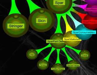
Figure 5 - XML visualised using Flash - See http://www.friendsofed.com/book.html?isbn=1590591585
Figure 6 shows the spar translated to Java and visualised using an applet.

Figure 6 - Java visualised by applet
The tree can also be translated into other languages; an alternative would be to translate into meta-languages.